IoT is gaining market rapidly. In recent years, many appliance, automobile manufactures have started adding “connected” features in their product line.
Most basic IoT implementation you can think of is, switching on|off an appliance over internet.
Let us see how this works and how you can build a IoT switch under 7 USD.
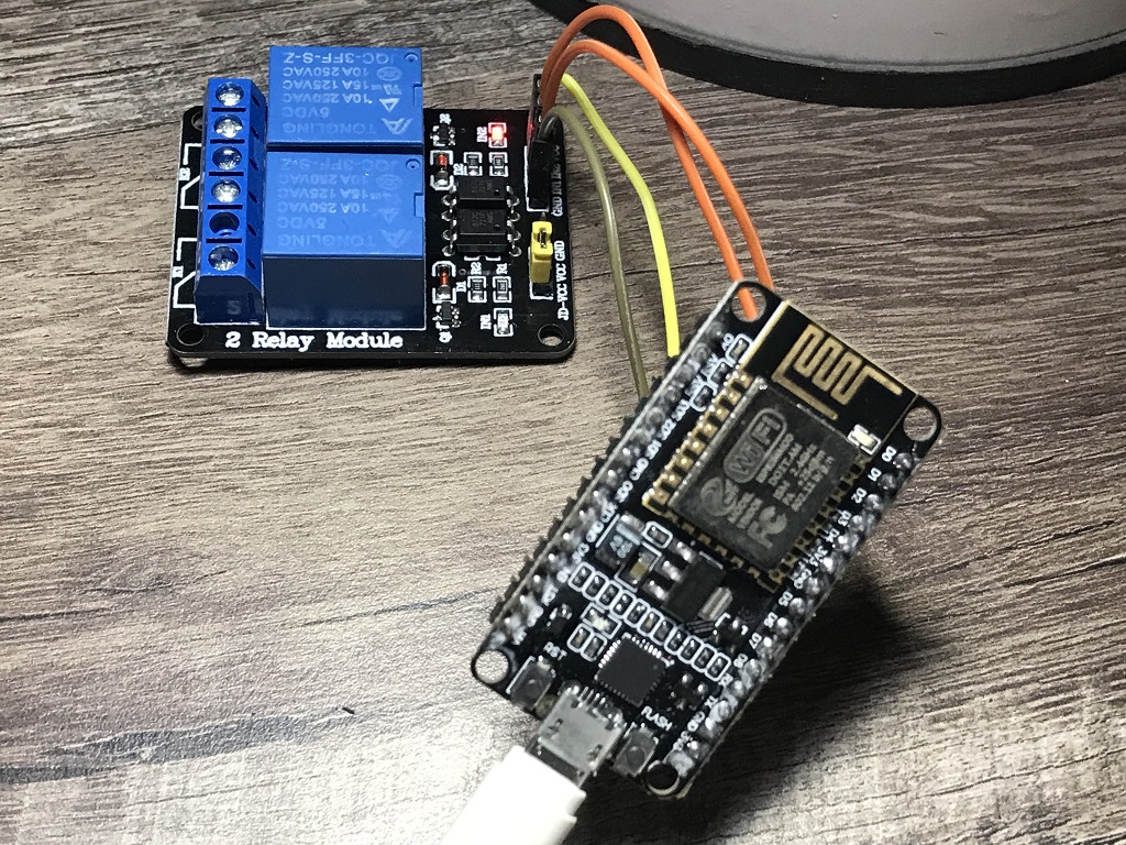
You need a NodeMCU board (flashed with micropython) and a relay (2 module in our case).
Connections between NodeMCU controller and relay:
- Relay VCC connected to 3.3V on NodeMCU.
- Relay GND connected to GND on NodeMCU.
- Relay IN1 connected to D1 pin (GPIO 5) on NodeMCU.
- Relay IN2 connected to D2 pin (GPIO 4) on NodeMCU.
Lets make solution a bit smart with all config parameters sitting in a json file, say config.json. config.json has WiFi, MQTT, relay-pin mappings.
{
   "wifi": { "username": "SSID", "password": "WiFi Password" },
   "mqtt": { "broker": "Broker IP", "mqttuser": "iotuser", "mqttpass": "iotpass", "mqttport": 1883, "mqttclient": "RELAYESP"},
   "relay": {
              "topic": "RLY",
              "relayports": [[4,1], [5,1]]
              "swpin": {"1": 4, "2": 5}
            },
   "location": {"city": "Gurgaon"}
}
Main python code, main.py, reads parameters from above json and accordingly connects to WiFi, MQTT.
from machine import Pin, ADC
from umqtt.robust import MQTTClient
import json
import time

with open('config.json') as cfg:
  cfgdata = json.load(cfg)

location = cfgdata.get('location').get('city')
substopic = cfgdata.get('relay').get('topic')
broker = cfgdata.get('mqtt').get('broker')
mqttuser = cfgdata.get('mqtt').get('mqttuser')
mqttpass = cfgdata.get('mqtt').get('mqttpass')
mqttport = cfgdata.get('mqtt').get('mqttport')
mqttclientID = cfgdata.get('mqtt').get('mqttclient')
client = MQTTClient(mqttclientID, broker, port=mqttport, user=mqttuser, password=mqttpass)

relayports = cfgdata.get('relay').get('relayports')
# Initialize relay with the state mentioned in config.json
for port in relayports:
   portid = port[0]
   portinit = port[1]
   Pin(portid, Pin.OUT).value(portinit)
   print("Init...", portid,portinit,Pin(portid, Pin.OUT).value())

def connectWiFi():
    import network
    username = cfgdata.get('wifi').get('username')
    password = cfgdata.get('wifi').get('password')
    sta_if = network.WLAN(network.STA_IF)
    if not sta_if.isconnected():
        print('connecting to network...')
        sta_if.active(True)
        sta_if.connect(username, password)
        while not sta_if.isconnected():
            pass
    print('network config:', sta_if.ifconfig())

def processmqtt(topic, message):
    message = json.loads(message)
    switch = message.get('SW')
    operation = message.get('ON')
    pin = cfgdata.get('relay').get('swpin').get(str(switch))
    print(topic, switch, pin, operation)
    opRelay(pin, operation)

def opRelay(pin, state):
    relay = Pin(pin, Pin.OUT)
    relay.value(state)

while True:
    connectWiFi()
    client = MQTTClient(mqttclientID, broker, port=mqttport, user=mqttuser, password=mqttpass)
    client.set_callback(processmqtt)
    client.connect()
    client.subscribe(substopic)
    print("waiting...", substopic)
    while True:
       try:
          client.check_msg()
       except:
          break
    client.disconnect()
Upload config.json and main.py on NodeMCU and restart controller.
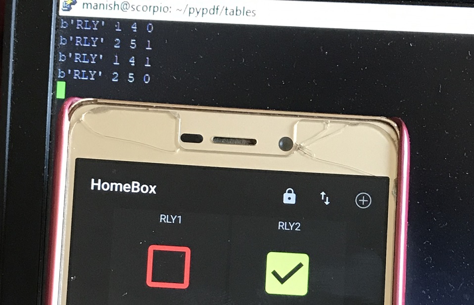
Using MQTT dash app on phone construct two switches.
{"SW": 1, "ON": 0}  <---Turn ON switch 1
{"SW": 1, "ON": 1}  <---Turn OFF switch 1

{"SW": 2, "ON": 0}  <---Turn ON switch 2
{"SW": 2, "ON": 1}  <---Turn OFF switch 2
Now operate switches from MQTT dash app on mobile and you will see relay going on|off. You will also see messages on serial terminal of microcontroller.
Related Posts